
How to Design a Balcony PV Microinverter: a 500 W Design Based on the GD32E515RET7
Bottom line: a balcony microinverter lives or dies on three things — MPPT accuracy, grid power quality and outdoor reliability. This design uses the GigaDevice GD32E515RET7 (Cortex-M33, 180 MHz, -40 to +105 °C industrial grade) as the main controller with a Boost + full-bridge topology, achieving MPPT tracking accuracy above 99.5%, grid current THD below 3% and 96.5% peak efficiency for a 500 W balcony PV system, with IP67 outdoor installation and Wi-Fi cloud monitoring built in.
1. What a balcony microinverter does
A balcony photovoltaic microinverter is a compact, high-reliability power conversion device designed for residential balcony distributed PV systems: it converts the DC output of PV modules into grid-compliant AC power for local consumption or grid feed-in.
Unlike a string inverter, a microinverter works at module level — one panel, one inverter. Each panel runs its own MPPT, so shading or orientation differences no longer drag down a whole string. The enclosure mounts on a balcony corner with IP67 protection, directly exposed to outdoor humidity and temperature swings.
This design uses the GigaDevice GD32E515RET7 as the main controller, taking full advantage of its high performance, low power consumption, rich peripherals and wide temperature range, combined with an efficient power conversion topology, to build a cost-effective solution for 500 W-class balcony PV systems.
2. System architecture
The system is built around the GD32E515RET7 with five functional blocks: DC sampling and MPPT control, power conversion, grid-tie control and power quality regulation, communication and monitoring, and protection.
flowchart LR
    PV["PV module<br/>22-60 V DC"] --> PROT["Anti-reverse / EMI + surge"]
    PROT --> BOOST["Boost converter<br/>MPPT tracking >99.5%"]
    BOOST --> INV["DC-AC full bridge 500 W<br/>SPWM + dead time"]
    INV --> FILT["Sine synthesis filter / EMC filter"]
    FILT --> GRID["Grid output<br/>211-264 Vac / 50-60 Hz"]
    MCU["GD32E515RET7 MCU<br/>180 MHz Cortex-M33<br/>MPPT / PLL / protection"] --> BOOST
    MCU --> INV
    WIFI["Wi-Fi module GD32VW553"] --> MCU
    WIFI --> CLOUD["2.4 G cloud / app monitoring"]
How each stage works:
- DC side: the PV output passes through an anti-reverse circuit; the ADC peripherals of the GD32E515RET7 sample voltage and current, and the built-in MPPT algorithm (perturb-and-observe or incremental conductance) outputs PWM to the Boost converter to track the maximum power point.
- Power conversion: the Boost output is converted to AC by a full-bridge inverter built from IGBTs/MOSFETs; the advanced timers (TIMER0/TIMER7) generate high-precision PWM with dead time.
- Grid-tie control: the ADC samples grid voltage and frequency; a software phase-locked loop (PLL) synchronizes output amplitude, frequency and phase with the grid, keeping THD below 3%.
- Communication and monitoring: a USART connects the Wi-Fi module to the cloud monitoring platform, uploading power, voltage, current and fault status; USB (USBHS peripheral) or CAN is available for local debugging and parameter configuration.
- Protection: the ADC, comparators (CMP) and timers monitor system status in real time for over/under-voltage, over-current, over/under-frequency, anti-islanding, overload and DC reverse-polarity protection, cutting the power path and reporting alarms on fault.
System framework diagram
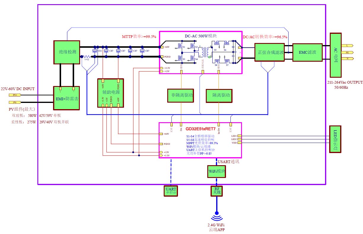
Figure: balcony microinverter system framework (22-60 V DC input → 500 W DC-AC conversion → 211-264 Vac / 50-60 Hz grid output, GD32E515RET7 main controller + Wi-Fi cloud monitoring)
3. Core hardware design (based on the GD32E515RET7)
The peripheral set of the GD32E515RET7 matches the microinverter requirements closely:
| Function block | GD32E515RET7 peripherals | What it does |
|---|---|---|
| DC sampling | 3× 12-bit ADC (2.5 MSPS) sampling PV voltage PV_V, PV current PV_I and Boost output current | Accurate DC-side parameters for the MPPT algorithm, sampling error ≤1% |
| MPPT control | Advanced timer TIMER0 (16-bit, complementary PWM) | 20 kHz PWM drives the Boost MOSFET, tracking accuracy >99.5% |
| Inversion and grid tie | Advanced timer TIMER7 (dead time, center-aligned PWM) + comparator CMP | SPWM drives the full bridge; PLL synchronizes with the grid, THD ❤️% |
| Grid parameter sampling | ADC samples grid voltage AC_V and current AC_I; a timer measures grid frequency | Real-time grid amplitude and frequency monitoring (50/60 Hz auto detection) |
| Communication | USART to the Wi-Fi module; USBHS (USB 2.0 high-speed) for local debugging | Cloud data upload, remote monitoring, parameter configuration and firmware update |
| Protection | External interrupt EXTI + timer fault delay + comparator CMP | Over/under-voltage, over-current, anti-islanding, overload protection, fault response <10 μs |
| Power management | Internal LDO + low-power modes (Sleep / Deep-sleep) | Reduces night-time standby consumption across day/night PV power swings |
Key component selection
- Power devices: a 650 V N-channel MOSFET for the Boost stage and a 650 V/15 A IGBT for the full bridge, matched to the 500 W rating and 60 Vdc input. See How to Select Power Devices for Home Storage / Inverters (Chinese) for the loss and voltage-margin method.
- Sampling: precision shunt resistors (0.01 Ω/1 W) with op-amps for current; a 1% resistor divider network for voltage.
- Communication module: GD32VW553 Wi-Fi module (2.4 GHz). Through the home router it reaches the cloud server, and the mobile app displays device status and all electrical data: power, energy, voltage and current.
- Filtering: electrolytic capacitors (3300 μF/63 V ×4) with 100 nF ceramics on the input; an LC filter network on the output, reducing EMI harmonics and providing lightning protection.
4. Software function modules
The firmware is modular, developed on RT-Thread (or a bare-metal architecture):
- MPPT module: incremental conductance method; the ADC samples PV voltage and current every 10 ms, the power/voltage change ratio locates the operating point relative to the MPP, and TIMER0 adjusts the PWM duty cycle. Tracking accuracy >99.5% under changing irradiance and temperature.
- Inversion and grid synchronization: SHRTIMER generates the SPWM waveform with configurable dead time (typically 200 ns) to prevent shoot-through; a software PLL locks to the grid voltage zero crossing with synchronization error below 0.5°, power factor -0.85 to 0.85 (lagging/leading).
- Data acquisition and processing: the DMA controller moves ADC data at high speed, offloading the CPU; data is filtered (moving average) and calibrated before feeding the control algorithms, status display and upload.
- Communication and monitoring: uplink through the USART/Wi-Fi module uploads generation data and alarms to the cloud platform, all visible in the app; downlink configures grid parameters and MPPT thresholds from the cloud; local USB supports debugging and firmware updates.
- Protection and fault handling: see the table below.
| Protection | Trigger condition and action |
|---|---|
| Over/under-voltage | ADC detects PV voltage (>62 V or <16 V) or grid voltage (>264 V or <198 V); EXTI interrupt shuts down PWM output |
| Over-current | Comparator CMP detects grid current >10 A; timer interrupt cuts the power path |
| Anti-islanding | Grid frequency anomaly (>60.5 Hz or <59.3 Hz) stops grid output within 100 ms |
| Overload | Output power >550 W sustained 500 ms reduces PWM duty cycle to limit output |
| DC reverse polarity | Hardware anti-reverse diode plus software polarity detection; startup is blocked when reversed |
On fault the system immediately shuts down PWM output and opens the grid-tie relay, uploads the fault code over Wi-Fi, and lights the LED fault indicator (different faults flash at different rates).
5. Key specifications
1. Microinverter specifications (500 W class)
| Category | Specification |
|---|---|
| PV input | Max recommended PV power 600 Wp; max DC open-circuit voltage 60 Vdc; max input current 25 Adc; MPPT range 25-45 Vdc (start-up ≥22 Vdc); tracking accuracy >99.5% |
| AC output | Rated output 500 W; peak 550 W; nominal grid voltage 220 Vac (single phase); allowed range 198-242 Vac (configurable); frequency range 59.3-60.5 Hz (auto detection, configurable); rated current 2.67 Aac; THD ❤️%; power factor -0.85 to 0.85 |
| Efficiency | Peak efficiency 96.5%; CEC weighted efficiency 96.0%; night-time consumption <50 mW |
| Mechanical and environment | Operating temperature -40 to +65 °C; storage -40 to +90 °C; protection IP67 (NEMA 6); size 230×250×31 mm; weight 2.5 kg; natural convection cooling (fanless) |
| Protection | Over/under-voltage, over/under-frequency, over-current, anti-islanding, overload, DC reverse polarity, over-temperature |
| Communication and compliance | Wi-Fi (GD32VW553 module, 2.4 GHz); cloud app monitoring; UL1741, CSA C22.2 No.107.1, IEC/EN 62109-1/2; IEEE 1547, NEC 2020 (690.12 rapid shutdown) |
2. GD32E515RET7 main controller specifications
Chip data from the GD32E515xx Datasheet Rev1.1 (June 2025); the official GigaDevice datasheet prevails.
| Category | Specification |
|---|---|
| Core and performance | Arm Cortex-M33 core up to 180 MHz; Thumb/Thumb-2 with DSP extension and FPU; NVIC interrupt controller |
| Memory | 512 KB Flash (0-4 wait states); 128 KB SRAM; 2 KB OTP (calibration data) |
| Analog | 3× 12-bit SAR ADC (2.5 MSPS, 16 channels, hardware oversampling); 3 comparators; 2 DACs (3 channels) |
| Timers | 2 advanced timers (TIMER0/TIMER7, complementary PWM + dead time); 1× 32-bit timer; 12× 16-bit general timers; 2 basic timers; SHRTIMER |
| Connectivity | 4 USART + 2 UART; 3 I2C (1 MHz); 3 SPI; 3 CAN; USBHS (USB 2.0 high-speed); SDIO |
| Others | TMU trigonometric acceleration unit; SQPI serial/quad parallel interface; DMA controller |
| Power and consumption | Supply 1.71-3.63 V; run current 23.25 mA (180 MHz, peripherals off); Sleep 9.21 mA; Deep-sleep 59.20 μA; standby 2.82 μA (RTC off) |
| Package and temperature | LQFP64 (0.5 mm pitch); operating temperature -40 to +105 °C (industrial); storage -65 to +150 °C; ESD 4 kV (HBM) / 500 V (CDM) |
6. Design advantages
- High-performance controller fit: the 180 MHz Cortex-M33 with DSP/FPU runs MPPT and PLL algorithms efficiently; 3× 2.5 MSPS ADCs and rich timers secure control precision.
- Reliability in outdoor environments: -40 to +105 °C industrial-grade controller, IP67 enclosure, multi-level hardware and software protection reduce the failure rate under balcony humidity and temperature swings.
- Cost and integration: on-chip ADCs, advanced timers, CAN, USBHS and SDIO remove external chips, cutting BOM cost and PCB area for the compact microinverter form factor.
- Flexible communication: Wi-Fi cloud link plus UART local debugging support generation statistics, remote grid parameter configuration and easy maintenance.
- Efficiency: MPPT tracking >99.5%, 96.5% peak efficiency and <50 mW night-time standby improve the user return.
7. Applications and installation
Typical scenarios: residential balcony PV systems with one or two 300 Wp modules feeding the household load or the grid; apartment and villa balcony systems where installation space is limited and no large-scale construction is possible.
Installation tips: wall-mount the microinverter at least 1.5 m above ground, out of direct sunlight and rain, with free airflow for natural convection; orient panels south at a 30-45° tilt where possible; use PV1-F solar cable and observe polarity; connect the AC output through a residual-current breaker compliant with local grid codes and reserve space for the communication antenna.
FAQ
Q1: How is a balcony microinverter different from a string inverter or a power optimizer?
A string inverter shares one MPPT across a whole string, so one shaded panel drags down all others. An optimizer does module-level MPPT but still needs a central inverter. A balcony microinverter is one inverter per panel: each module tracks its own maximum power point and feeds the grid independently, and the system stays below 60 Vdc — safer to install and ideal for balconies with one or two panels and no freedom of orientation.
Q2: Why choose the GD32E515RET7 as the microinverter controller?
Four matches: the 180 MHz Cortex-M33 with DSP/FPU runs incremental-conductance MPPT and a software PLL comfortably; two advanced timers (TIMER0/TIMER7) with complementary PWM and dead time cover the Boost and full-bridge stages; 3× 2.5 MSPS 12-bit ADCs meet the synchronized DC- and AC-side sampling accuracy; and the -40 to +105 °C industrial temperature grade with an LQFP64 package suits outdoor heat and automated assembly. On-chip CAN, USBHS and SDIO also remove external interface chips.
Q3: How is grid power quality guaranteed?
Three stages: SHRTIMER generates the SPWM with a typical 200 ns dead time to prevent shoot-through; the software PLL synchronizes phase and frequency to the grid voltage zero crossing with error below 0.5°; and the LC output filter keeps grid current THD below 3% with power factor between -0.85 and 0.85. Voltage and frequency windows (198-242 Vac / 59.3-60.5 Hz) are configurable to local grid codes.
Q4: How does anti-islanding work?
The system continuously monitors grid frequency; an excursion beyond 60.5 Hz or below 59.3 Hz is judged as islanding and grid output stops within 100 ms. Together with over/under-voltage, over-current and overload protection, faults shut down PWM, open the grid-tie relay, upload the fault code over Wi-Fi and flash the LED indicator by fault type.
Q5: How are monitoring and debugging implemented?
The GD32VW553 Wi-Fi module (2.4 GHz) connects through the home router to the cloud; the mobile app shows real-time power, daily and cumulative energy, voltage, current and fault status. Local debugging uses UART or the USBHS (USB 2.0 high-speed) interface for parameter configuration and firmware updates.
Related solutions
- How to Select an MCU for BMS: GD32 Selection Guide (Chinese)
- How to Design an MPPT Controller (Chinese)
- How to Select IGBT/MOSFET for Home Storage Inverters (Chinese)
- Low-Voltage BLDC Control Solution (Chinese)
Contact us
For GD32 controller selection support, sample requests or a matching power device (MOSFET/IGBT) cross-reference for your microinverter or home-storage project, contact us.
Shenzhen Intek Technology Co., Ltd — electronic components distributor and system solutions provider Tel / WeChat: 136-3264-8484 Address: 4F, Building 2, Jingwei Center, No. 309 Pingan Avenue, Pinghu Street, Longgang District, Shenzhen, China Website: www.intek.vip
Disclaimer: This article is intended for technical communication only. System-level specifications come from the solution design document (subject to final product measurement and certification); chip specifications come from the GD32E515xx Datasheet Rev1.1 (the official GigaDevice datasheet prevails). It does not constitute selection, purchasing or other business advice.